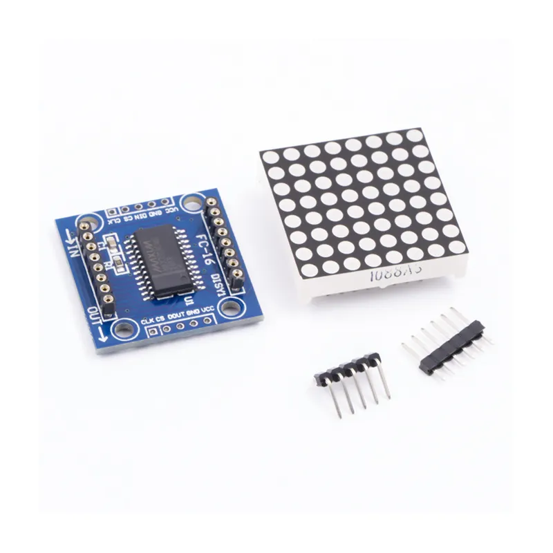
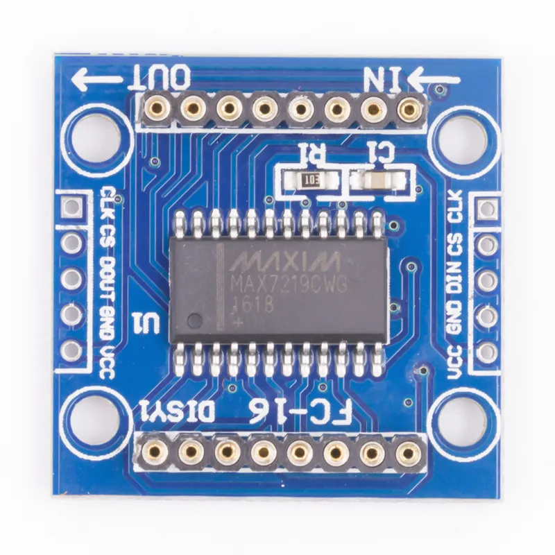
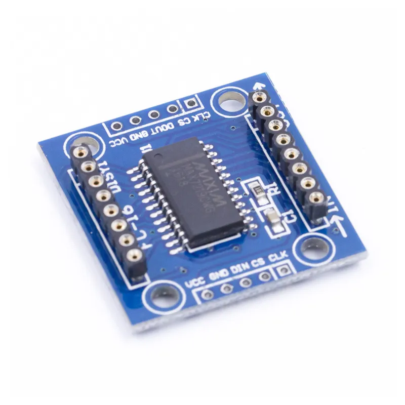
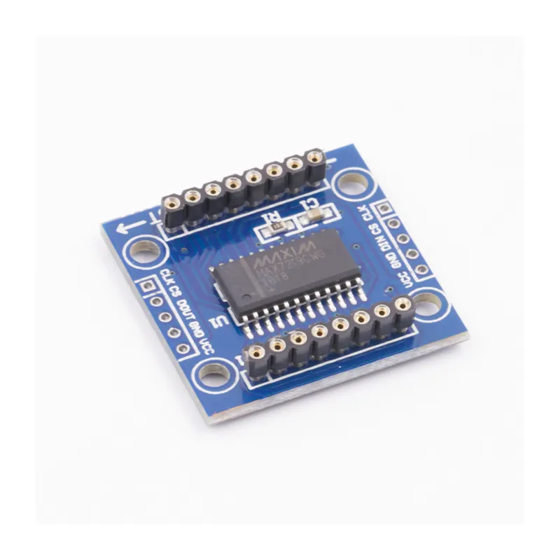
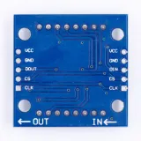
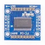
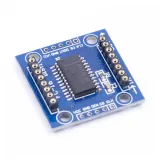
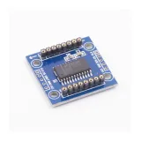
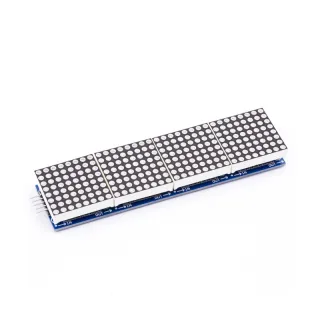
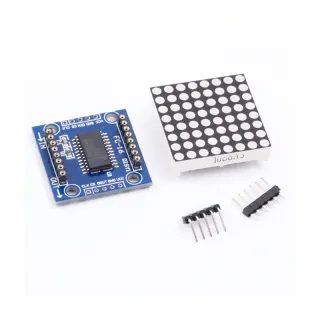
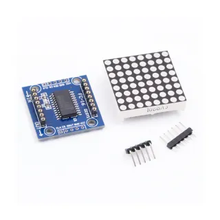
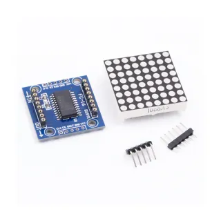
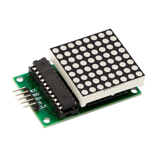
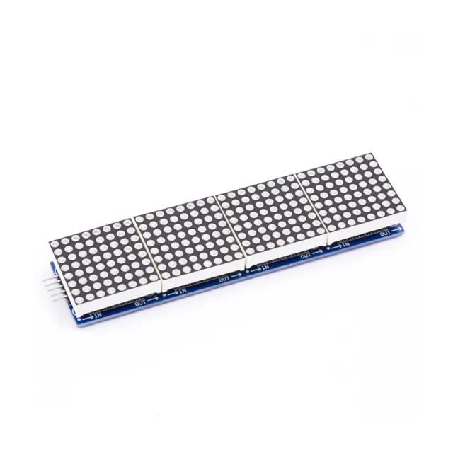
8x8 LED-matrixmodule voor Arduino DIY-projecten met SPI-aansturing en cascadeerbare modules.
SKU: OT3643 Número do artigo: AA185 EAN: 8720618489722 Localização: H05.05
Alternativa
Matriz LED 32x8 com módulo MAX7219
€ 6,25
Ver esta alternativa
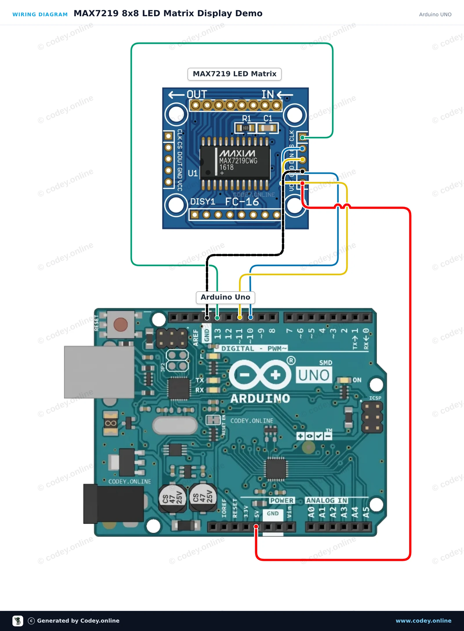
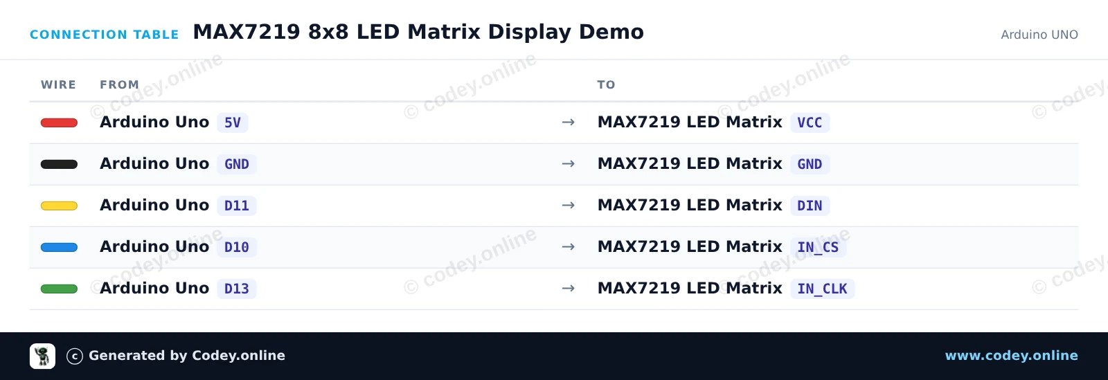
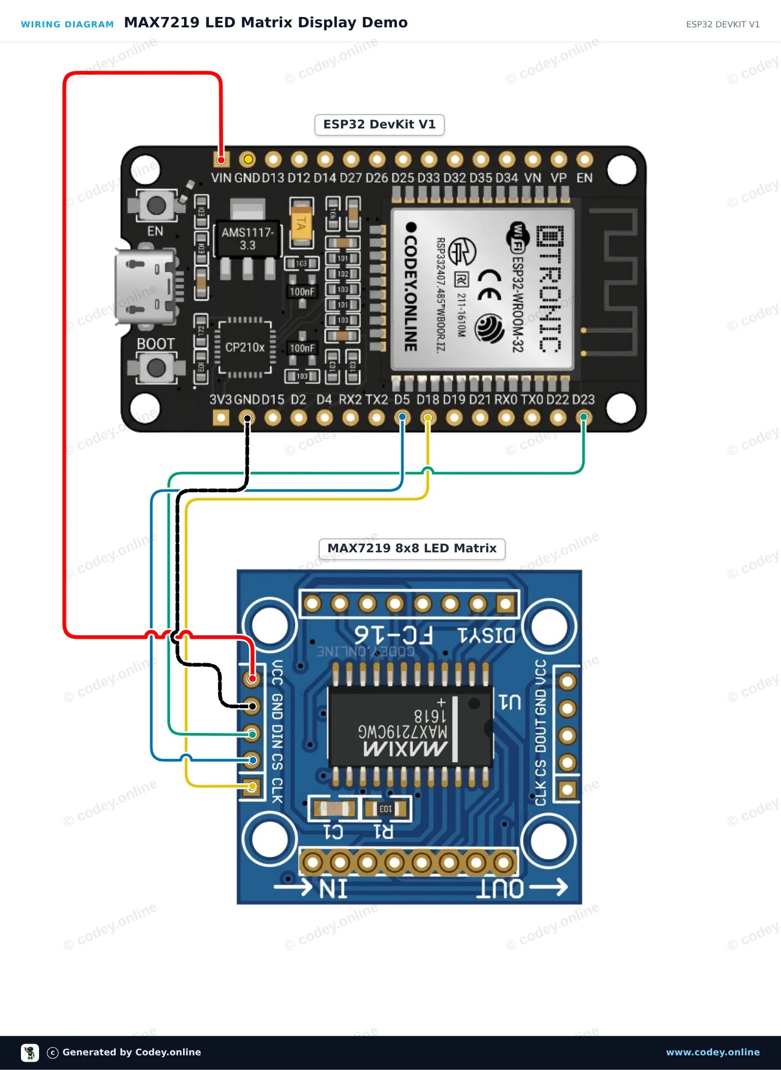
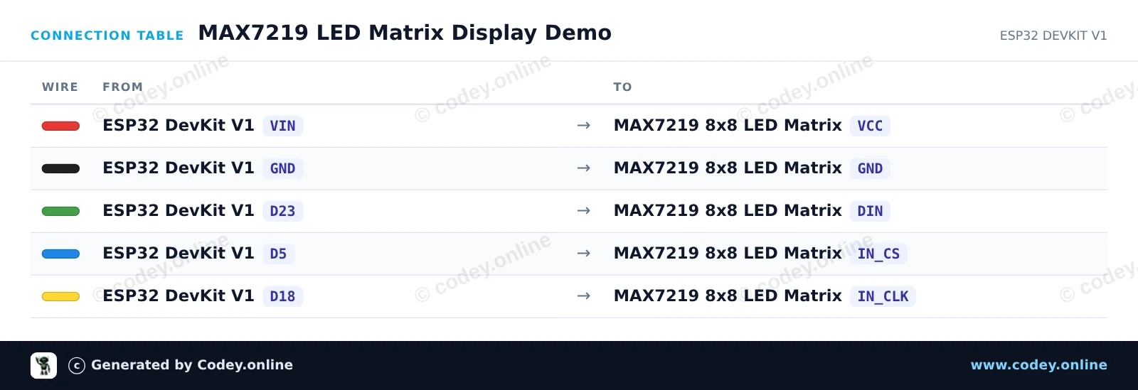
Como ligar o Módulo LED Matrix MAX7219 Vermelho a um Arduino UNO ou ESP32, com um sketch de exemplo que podes carregar já.
This project demonstrates how to control an 8x8 LED matrix using the MAX7219 driver chip. It initializes the display and cycles through displaying a smiley face, a heart icon, and a scanning pixel pattern.
/*
* ==================================================================
* Generated by Codey.online — https://www.codey.online
* ==================================================================
* Project : MAX7219 8x8 LED Matrix Display Demo
* Board : Arduino UNO (arduino:avr:uno)
* Parts : LED Matrix Module MAX7219
* Libraries : LedControl 1.0.6
*
* Codey Online is an AI-powered browser IDE for Arduino and ESP32.
* Describe your project and Codey writes the code, draws the wiring
* diagram and uploads it to your board, straight from the browser.
* This code is free to use, modify and share, without warranty.
* ==================================================================
*/
#include <LedControl.h>
const int DIN_PIN = 11;
const int CS_PIN = 10;
const int CLK_PIN = 13;
LedControl lc = LedControl(DIN_PIN, CLK_PIN, CS_PIN, 1);
// 8x8 bitmap patterns
const byte SMILEY[8] = {
0b00111100,
0b01000010,
0b10100101,
0b10000001,
0b10100101,
0b10011001,
0b01000010,
0b00111100
};
const byte HEART[8] = {
0b00000000,
0b01100110,
0b11111111,
0b11111111,
0b01111110,
0b00111100,
0b00011000,
0b00000000
};
void drawPattern(const byte pattern[8]) {
for (int row = 0; row < 8; row++) {
lc.setRow(0, row, pattern[row]);
}
}
void setup() {
Serial.begin(115200);
Serial.println(F("MAX7219 LED Matrix Demo"));
lc.shutdown(0, false); // Wake up display
lc.setIntensity(0, 5); // Brightness (0-15)
lc.clearDisplay(0);
}
void loop() {
// Show smiley face
drawPattern(SMILEY);
delay(2000);
// Show heart
drawPattern(HEART);
delay(2000);
// Clear display
lc.clearDisplay(0);
delay(500);
// Scan a single pixel across all rows and columns
for (int row = 0; row < 8; row++) {
for (int col = 0; col < 8; col++) {
lc.setLed(0, row, col, true);
delay(30);
lc.setLed(0, row, col, false);
}
}
delay(500);
}
Bibliotecas necessárias: LedControl 1.0.6
Wiring diagram and example code generated by Codey.online — https://www.codey.online
This project demonstrates driving an 8x8 MAX7219 LED matrix display using the ESP32 hardware SPI interface. The sketch initializes the display registers and alternates between showing a heart icon and a smiley face.
/*
* ==================================================================
* Generated by Codey.online — https://www.codey.online
* ==================================================================
* Project : MAX7219 LED Matrix Display Demo
* Board : ESP32 DEVKIT V1 (esp32:esp32:esp32doit-devkit-v1)
* Parts : LED Matrix Module MAX7219
* Libraries : none (built-in)
*
* Codey Online is an AI-powered browser IDE for Arduino and ESP32.
* Describe your project and Codey writes the code, draws the wiring
* diagram and uploads it to your board, straight from the browser.
* This code is free to use, modify and share, without warranty.
* ==================================================================
*/
#include <SPI.h>
const int PIN_CS = 5;
// MAX7219 register addresses
const byte REG_NOOP = 0x00;
const byte REG_DIGIT0 = 0x01;
const byte REG_DECODEMODE = 0x09;
const byte REG_INTENSITY = 0x0A;
const byte REG_SCANLIMIT = 0x0B;
const byte REG_SHUTDOWN = 0x0C;
const byte REG_DISPLAYTEST = 0x0F;
const byte heart[8] = {
0b00000000,
0b01100110,
0b11111111,
0b11111111,
0b11111111,
0b01111110,
0b00111100,
0b00011000
};
const byte smile[8] = {
0b00111100,
0b01000010,
0b10100101,
0b10000001,
0b10100101,
0b10011001,
0b01000010,
0b00111100
};
void writeRegister(byte reg, byte data) {
digitalWrite(PIN_CS, LOW);
SPI.transfer(reg);
SPI.transfer(data);
digitalWrite(PIN_CS, HIGH);
}
void showBitmap(const byte bitmap[8]) {
for (byte i = 0; i < 8; i++) {
writeRegister(REG_DIGIT0 + i, bitmap[i]);
}
}
void setup() {
Serial.begin(115200);
Serial.println("MAX7219 LED Matrix Demo Started");
pinMode(PIN_CS, OUTPUT);
digitalWrite(PIN_CS, HIGH);
SPI.begin();
writeRegister(REG_DISPLAYTEST, 0x00); // Normal operation
writeRegister(REG_SCANLIMIT, 0x07); // Display all 8 rows
writeRegister(REG_DECODEMODE, 0x00); // No BCD decoding (raw matrix)
writeRegister(REG_INTENSITY, 0x04); // Brightness (0x00 to 0x0F)
writeRegister(REG_SHUTDOWN, 0x01); // Wake up from shutdown
}
void loop() {
showBitmap(heart);
delay(1000);
showBitmap(smile);
delay(1000);
}
Wiring diagram and example code generated by Codey.online — https://www.codey.online
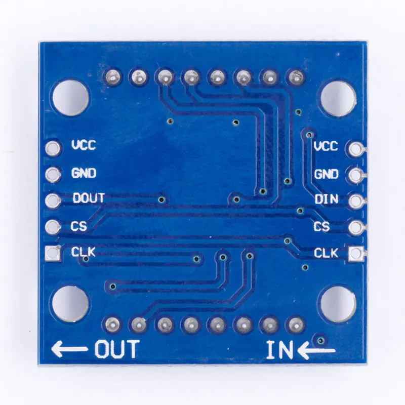
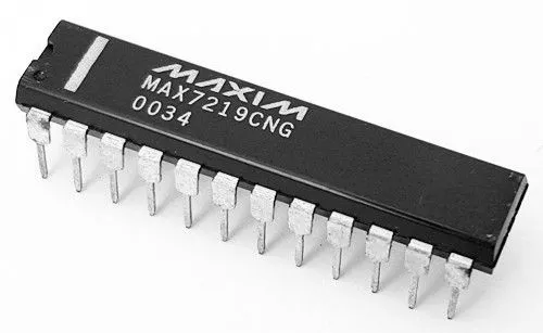
MAX7219 é um IC utilizado para o controlo de painéis LED com cátodo comum, displays de 7 segmentos e indicadores de nível que comunicam através da interface SPI. Esta placa tem um display LED matrix 8x8. Vários módulos podem ser encadeados em cascata com a ajuda de ligações header.
Especificações:

| Dimensões | 3,2 cm x 3,2 cm x 1,3 cm |
|---|---|
| Tensão de operação | 5V |
| Compatibilidade | Compatibel met Arduino UNO R3 / Arduino Mega2560 |
| IC do driver | MAX7219 |
| Tensão lógica da interface | 5V |
| Tipo de interface | SPI |
| Conexões | VCC, GND, DIN, CS, CLK |
| Bibliotecas para Arduino | Max72xxPanel en Adafruit_GFX |
| Cor do LED | rood |
| Tamanho do LED | 5 mm |
| Número de nós em cascata | 32 (MAX) |
| Furos de montagem | 4 x 3 mm |
| Corrente de trabalho | 250mA (MAX) |
Ótimo produto.
Não ficas satisfeito? Tens 30 dias após a receção para devolver o produto.
Tudo sobre devoluções
Módulo LED Matrix MAX7219 Vermelho