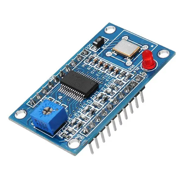
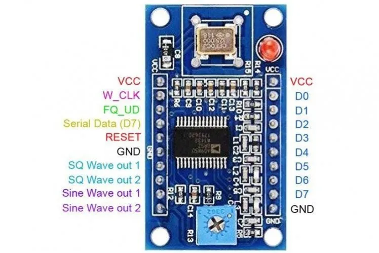
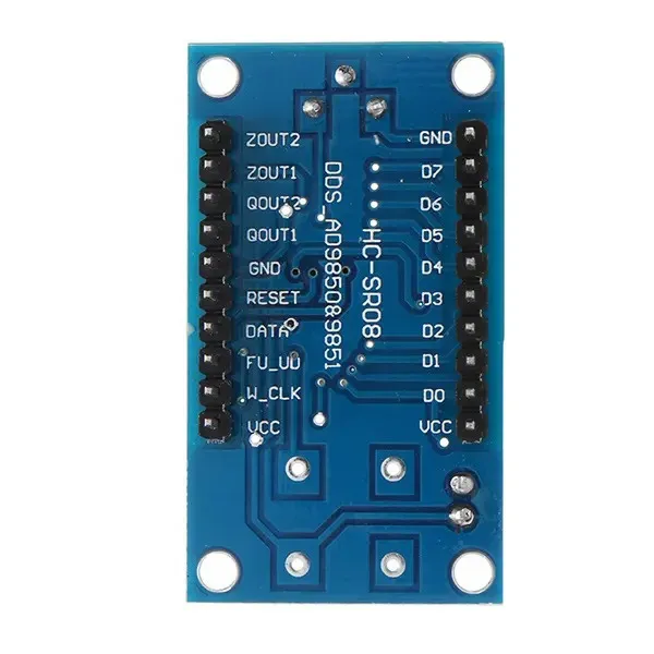
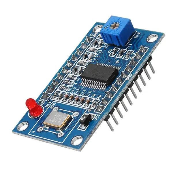
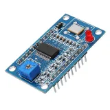
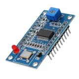
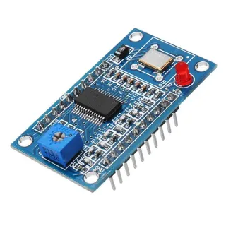
DDS signaalgenerator-module voor Arduino en zelfbouw van flexibele frequentie- of functiegeneratoren.
SKU: OT3459 Número do artigo: NA416 EAN: 8720618690838 Localização: E06.05
Alternativa
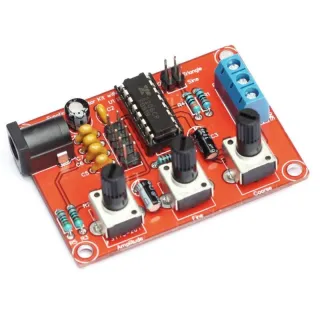
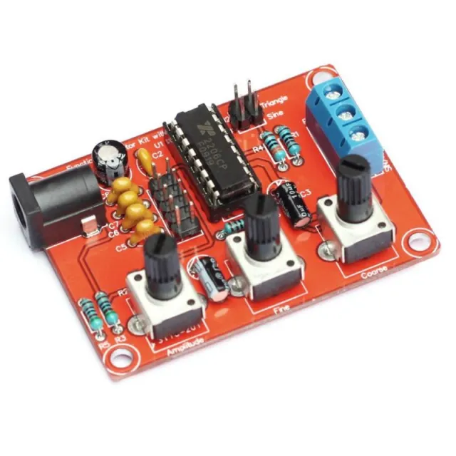
Kit DIY Gerador de Sinal XR2206
€ 7,80
Ver esta alternativa
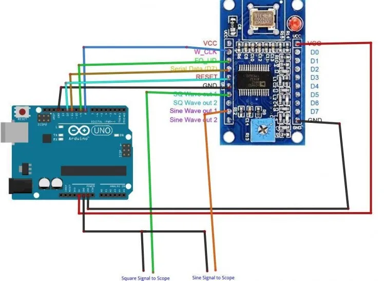
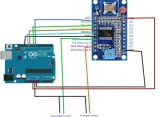
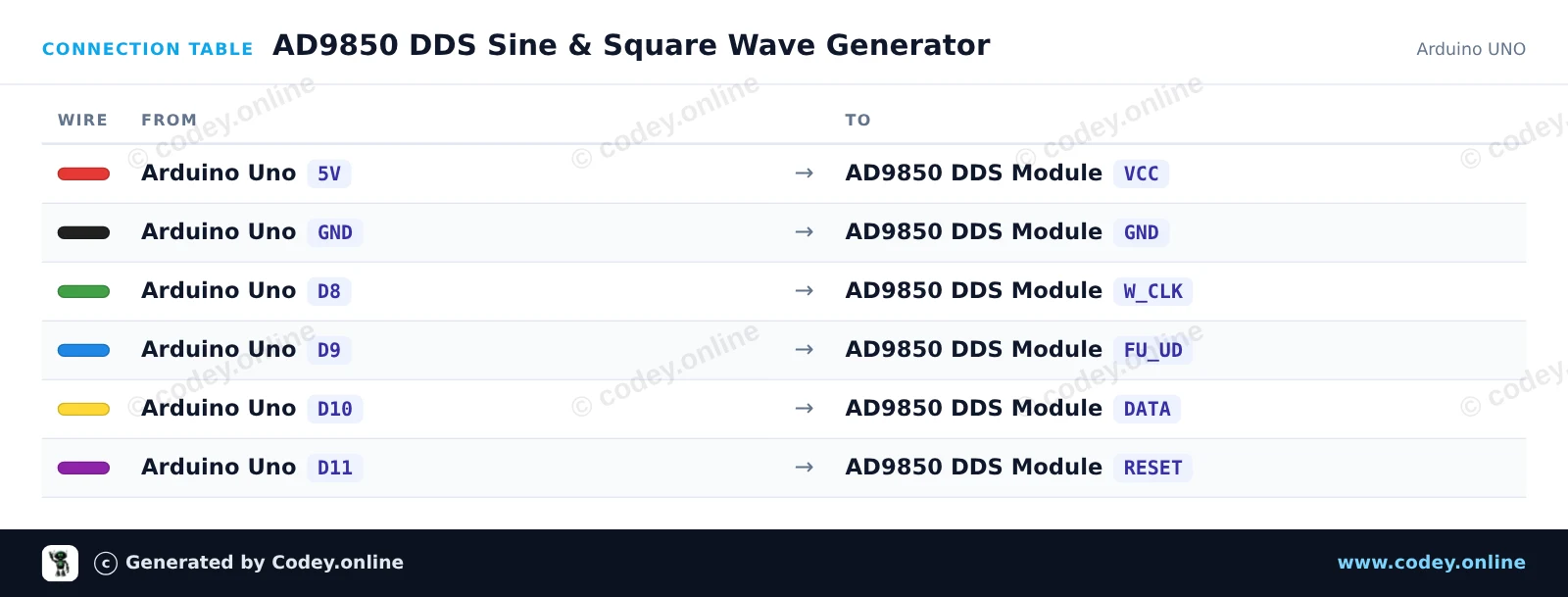
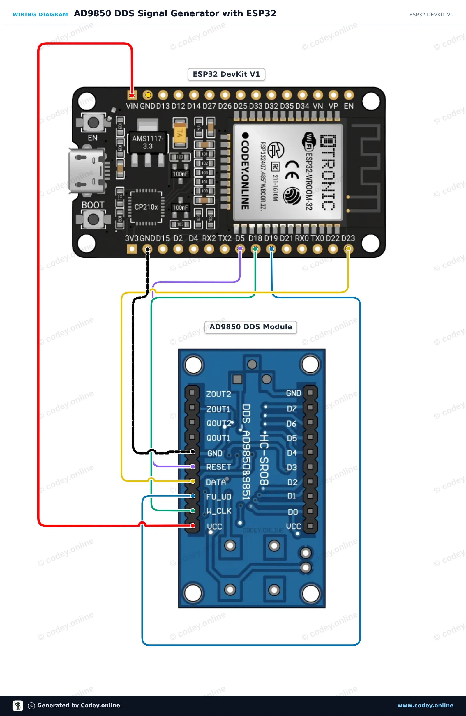
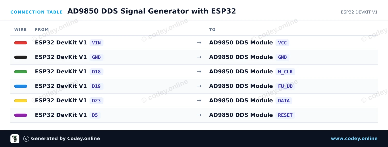
Como ligar o Módulo gerador de sinal DDS AD9850 a um Arduino UNO ou ESP32, com um sketch de exemplo que podes carregar já.
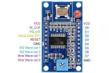
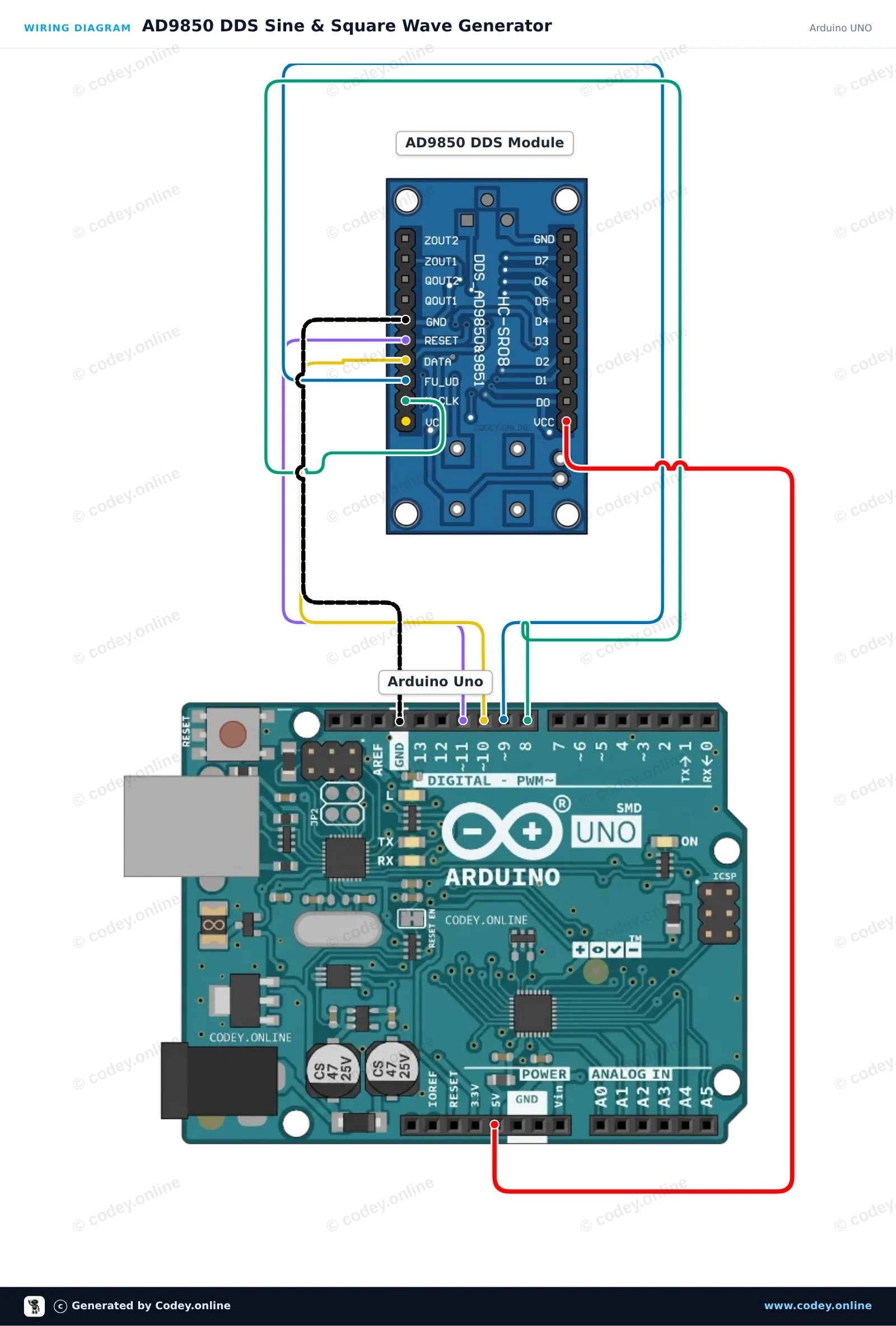
This project controls an AD9850 DDS module via a 4-wire serial interface to generate precise sine and square wave frequencies. The Arduino initializes the DDS module and periodically switches the output frequency between 1 kHz, 10 kHz, and 100 kHz. Connect an oscilloscope or frequency counter to ZOUT1 (sine wave) or QOUT1 (square wave) to inspect the output signal.
/*
* ==================================================================
* Generated by Codey.online — https://www.codey.online
* ==================================================================
* Project : AD9850 DDS Sine & Square Wave Generator
* Board : Arduino UNO (arduino:avr:uno)
* Parts : AD9850 DDS Signal Generator Module
* Libraries : none (built-in)
*
* Codey Online is an AI-powered browser IDE for Arduino and ESP32.
* Describe your project and Codey writes the code, draws the wiring
* diagram and uploads it to your board, straight from the browser.
* This code is free to use, modify and share, without warranty.
* ==================================================================
*/
const int PIN_W_CLK = 8;
const int PIN_FQ_UD = 9; // Labeled FU_UD on module
const int PIN_DATA = 10;
const int PIN_RESET = 11;
const unsigned long AD9850_REF_CLOCK = 125000000UL; // 125 MHz reference oscillator
void pulsePin(int pin) {
digitalWrite(pin, HIGH);
delayMicroseconds(1);
digitalWrite(pin, LOW);
delayMicroseconds(1);
}
void ad9850Reset() {
digitalWrite(PIN_RESET, HIGH);
delayMicroseconds(1);
digitalWrite(PIN_RESET, LOW);
delayMicroseconds(1);
pulsePin(PIN_W_CLK);
pulsePin(PIN_FQ_UD);
}
void ad9850SetFrequency(double freqHz) {
// Calculate 32-bit tuning word: (freq * 2^32) / ReferenceClock
uint32_t tuningWord = (uint32_t)((freqHz * 4294967296.0) / (double)AD9850_REF_CLOCK);
// Transmit 32-bit frequency tuning word (LSB first)
for (int i = 0; i < 32; i++) {
digitalWrite(PIN_DATA, (tuningWord >> i) & 0x01);
pulsePin(PIN_W_CLK);
}
// Transmit 8 control/phase bits (all 0 for normal operation)
for (int i = 0; i < 8; i++) {
digitalWrite(PIN_DATA, LOW);
pulsePin(PIN_W_CLK);
}
// Latch the updated frequency into the DDS core
pulsePin(PIN_FQ_UD);
}
void setup() {
pinMode(PIN_W_CLK, OUTPUT);
pinMode(PIN_FQ_UD, OUTPUT);
pinMode(PIN_DATA, OUTPUT);
pinMode(PIN_RESET, OUTPUT);
digitalWrite(PIN_W_CLK, LOW);
digitalWrite(PIN_FQ_UD, LOW);
digitalWrite(PIN_DATA, LOW);
digitalWrite(PIN_RESET, LOW);
Serial.begin(115200);
while (!Serial) {
;
}
Serial.println(F("AD9850 DDS Generator Initialized"));
ad9850Reset();
}
void loop() {
const double testFrequencies[] = {1000.0, 10000.0, 100000.0};
for (int i = 0; i < 3; i++) {
double freq = testFrequencies[i];
ad9850SetFrequency(freq);
Serial.print(F("Output frequency set to: "));
Serial.print(freq);
Serial.println(F(" Hz"));
delay(3000);
}
}
Wiring diagram and example code generated by Codey.online — https://www.codey.online
This project generates precise sine and square wave signals using the AD9850 DDS module controlled by an ESP32. The sketch steps through a sequence of frequencies (1 kHz, 10 kHz, 100 kHz, and 1 MHz) every 3 seconds. Connect an oscilloscope or frequency counter to ZOUT1 for a sine wave or QOUT1 for a square wave output.
/*
* ==================================================================
* Generated by Codey.online — https://www.codey.online
* ==================================================================
* Project : AD9850 DDS Signal Generator with ESP32
* Board : ESP32 DEVKIT V1 (esp32:esp32:esp32doit-devkit-v1)
* Parts : AD9850 DDS Signal Generator Module
* Libraries : none (built-in)
*
* Codey Online is an AI-powered browser IDE for Arduino and ESP32.
* Describe your project and Codey writes the code, draws the wiring
* diagram and uploads it to your board, straight from the browser.
* This code is free to use, modify and share, without warranty.
* ==================================================================
*/
// AD9850 DDS Signal Generator Demo on ESP32
const int W_CLK_PIN = 18;
const int FU_UD_PIN = 19;
const int DATA_PIN = 23;
const int RESET_PIN = 5;
// 125 MHz reference clock crystal on board
const double REF_CLK = 125000000.0;
const double testFrequencies[] = {1000.0, 10000.0, 100000.0, 1000000.0};
const int numFrequencies = sizeof(testFrequencies) / sizeof(testFrequencies[0]);
int currentFreqIndex = 0;
void pulseHigh(int pin) {
digitalWrite(pin, HIGH);
delayMicroseconds(1);
digitalWrite(pin, LOW);
delayMicroseconds(1);
}
void resetAD9850() {
pulseHigh(RESET_PIN);
pulseHigh(W_CLK_PIN);
pulseHigh(FU_UD_PIN); // Enable serial load mode
}
void sendFrequency(double frequency) {
uint32_t tuningWord = (uint32_t)((frequency * 4294967296.0) / REF_CLK);
// Send 32-bit frequency tuning word (LSB first)
for (int i = 0; i < 32; i++) {
digitalWrite(DATA_PIN, (tuningWord >> i) & 0x01);
pulseHigh(W_CLK_PIN);
}
// Send 8 control/phase bits (0x00 for 0 phase offset)
for (int i = 0; i < 8; i++) {
digitalWrite(DATA_PIN, LOW);
pulseHigh(W_CLK_PIN);
}
// Latch new frequency to output
pulseHigh(FU_UD_PIN);
}
void setup() {
Serial.begin(115200);
delay(500);
Serial.println("AD9850 DDS Signal Generator Initializing...");
pinMode(W_CLK_PIN, OUTPUT);
pinMode(FU_UD_PIN, OUTPUT);
pinMode(DATA_PIN, OUTPUT);
pinMode(RESET_PIN, OUTPUT);
digitalWrite(W_CLK_PIN, LOW);
digitalWrite(FU_UD_PIN, LOW);
digitalWrite(DATA_PIN, LOW);
digitalWrite(RESET_PIN, LOW);
resetAD9850();
Serial.println("AD9850 ready!");
}
void loop() {
double freq = testFrequencies[currentFreqIndex];
sendFrequency(freq);
Serial.print("Output frequency set to: ");
Serial.print(freq, 0);
Serial.println(" Hz");
currentFreqIndex = (currentFreqIndex + 1) % numFrequencies;
delay(3000);
}
Wiring diagram and example code generated by Codey.online — https://www.codey.online
Geradores de sinal/geradores de funções são super úteis, desde RF até lógica embarcada, mas normalmente não são muito baratos.
Boas notícias: com este Módulo DDS AD9850, você pode criar, com alguma montagem, o seu próprio gerador de frequência Arduino flexível, funcional e fácil de usar!
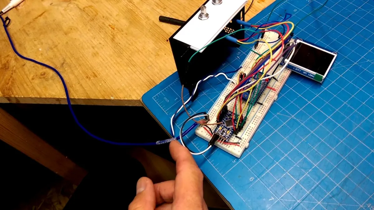
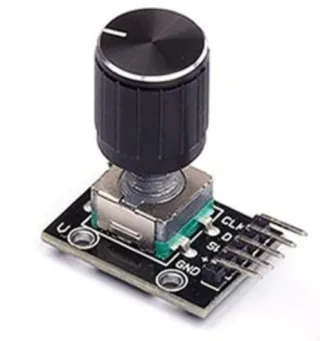
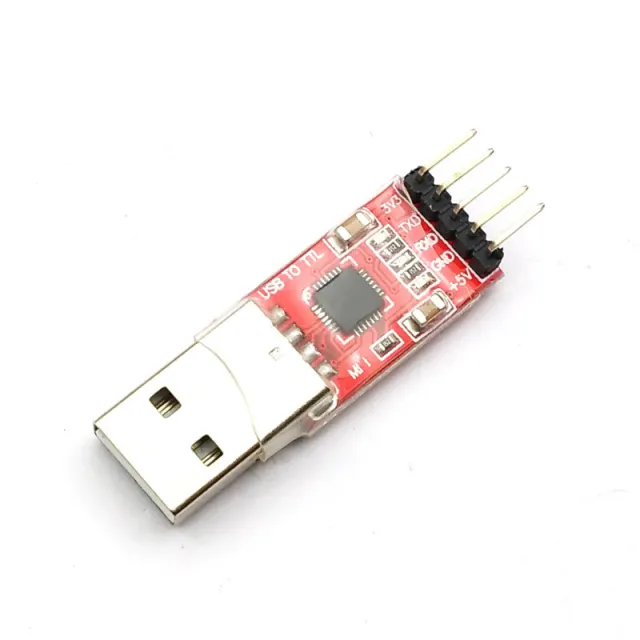
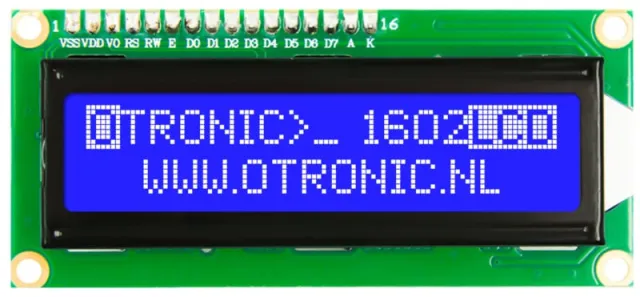
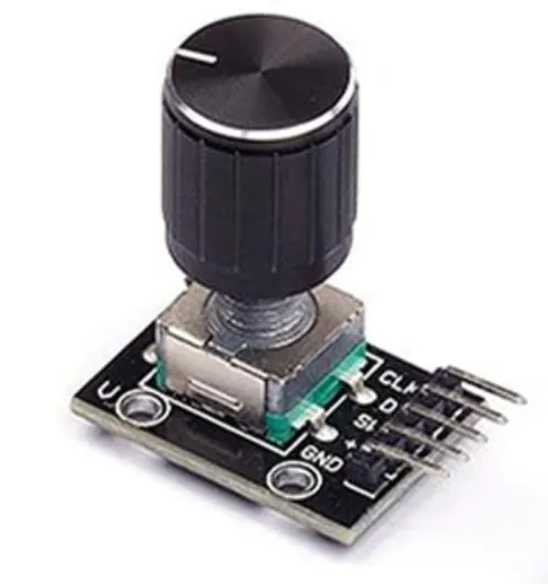
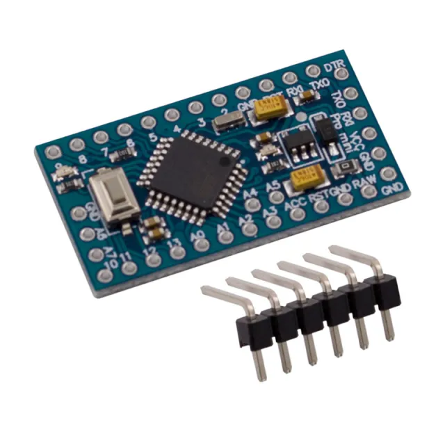
Com um display LED, um potenciômetro rotativo e um Arduino você pode criar um gerador de sinal independente. (Não se esqueça de adquirir um conversor CP2102 USB para TTL Serial caso ainda não tenha um em casa)
Também pode optar por combiná-lo apenas com Arduino Uno numa breadboard.
Uma rota completamente diferente é usar este módulo para criar o seu próprio Software Defined Radio (SDR).
Em suma, um ótimo módulo para começar a trabalhar!
Características:
APLICAÇÕES:
| Alimentação | 3,3 V ou 5 V |
|---|---|
| Frequência de clock | 125 MHz |
| Potência | 380 mW @ 125 MHz (5 V); 155 mW @ 110 MHz (3,3 V) |
| Modelo | AD9850 |
| Interface de controle simplificada | parallelle byte of serieel Laadformaat |
| Baixo consumo | 380 mW @ 125 MHz (5 V); 155 mW @ 110 MHz (3,3 V) |
| Número de derivações | 28 |
Excelente
Não ficas satisfeito? Tens 30 dias após a receção para devolver o produto.
Tudo sobre devoluções
Módulo gerador de sinal DDS AD9850