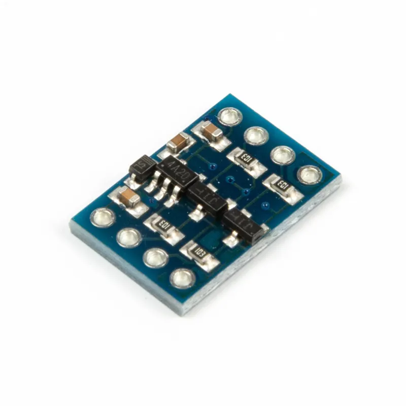
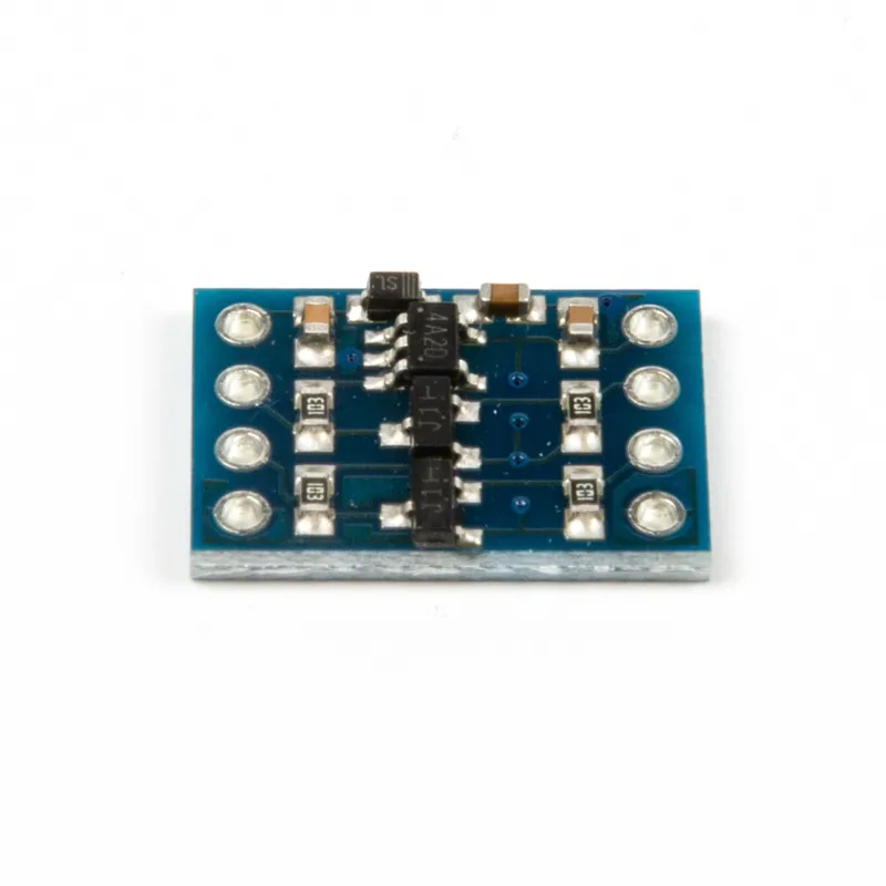
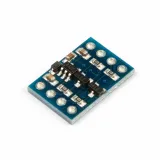
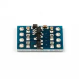
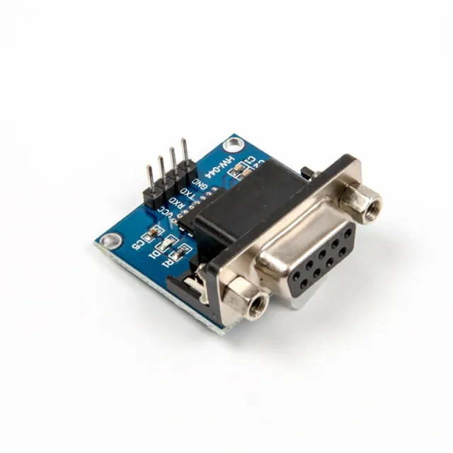
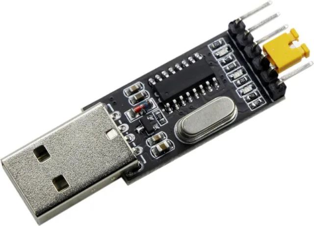
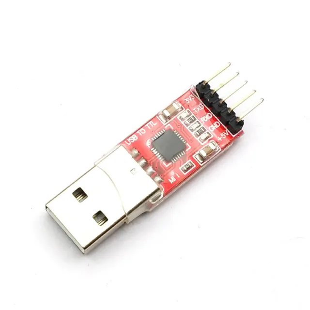
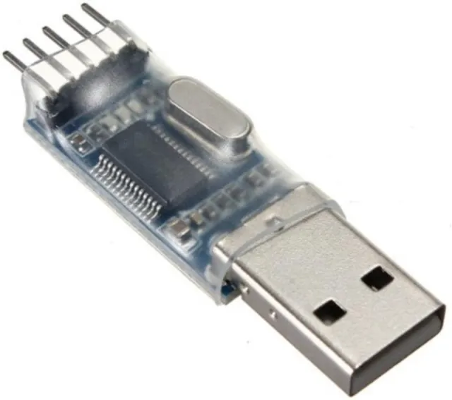
Bi-directionele logic level converter voor 5V-systemen met 3.3V I2C of UART, geschikt voor Arduino en andere modules.
SKU: ot8520 Número do artigo: NA018 EAN: 8720828223239 Localização: D01.02
Alternativa
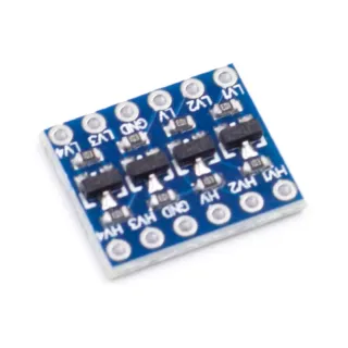
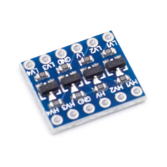
Conversor de nível de tensão lógica de 4 canais
€ 0,80
Ver esta alternativa
Como ligar o Conversor de Nível Lógico I2C-UART Bidirecional 5V-3.3V 2 canais a um Arduino UNO ou ESP32, com um sketch de exemplo que podes carregar já.
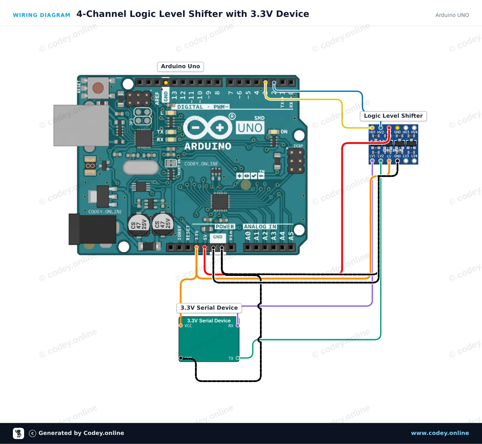
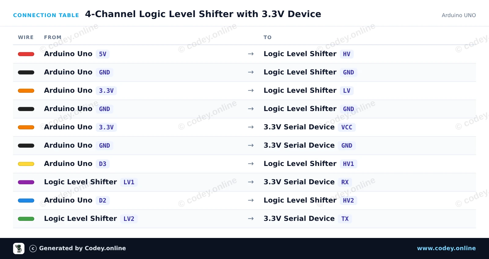
This circuit safely connects the 5V Arduino Uno to a 3.3V serial device using the 4-channel bidirectional logic level shifter. The Arduino sends and receives serial data via software serial (pins 2 and 3) while the level shifter translates signals between 5V (HV) and 3.3V (LV). Open the Serial Monitor at 115200 baud to monitor communications.
/*
* ==================================================================
* Generated by Codey.online — https://www.codey.online
* ==================================================================
* Project : 4-Channel Logic Level Shifter with 3.3V Device
* Board : Arduino UNO (arduino:avr:uno)
* Parts : Logic Level Shifter 4-channel
* Libraries : none (built-in)
*
* Codey Online is an AI-powered browser IDE for Arduino and ESP32.
* Describe your project and Codey writes the code, draws the wiring
* diagram and uploads it to your board, straight from the browser.
* This code is free to use, modify and share, without warranty.
* ==================================================================
*/
#include <SoftwareSerial.h>
// Arduino Uno pins connected to the HV (5V) side of the level shifter
const int rxPin = 2; // HV2 (receives translated 5V from 3.3V device TX)
const int txPin = 3; // HV1 (transmits 5V to be translated to 3.3V device RX)
SoftwareSerial deviceSerial(rxPin, txPin);
void setup() {
Serial.begin(115200);
deviceSerial.begin(9600);
Serial.println(F("Logic Level Shifter Demo Initialized."));
Serial.println(F("Forwarding serial data between USB and 3.3V device..."));
}
void loop() {
// Forward data from USB Serial to 3.3V device
if (Serial.available()) {
char c = Serial.read();
deviceSerial.write(c);
}
// Forward data from 3.3V device to USB Serial
if (deviceSerial.available()) {
char c = deviceSerial.read();
Serial.write(c);
}
}
Wiring diagram and example code generated by Codey.online — https://www.codey.online
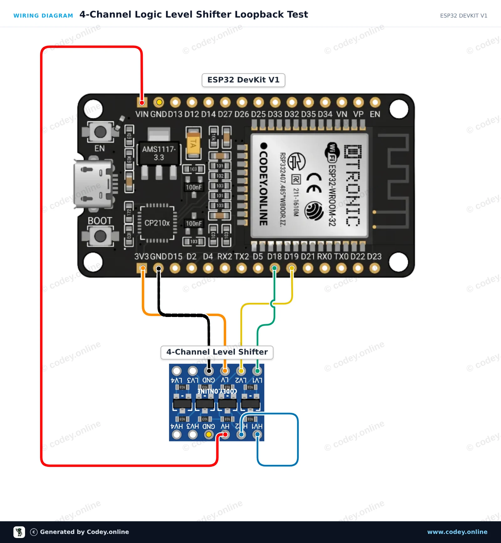
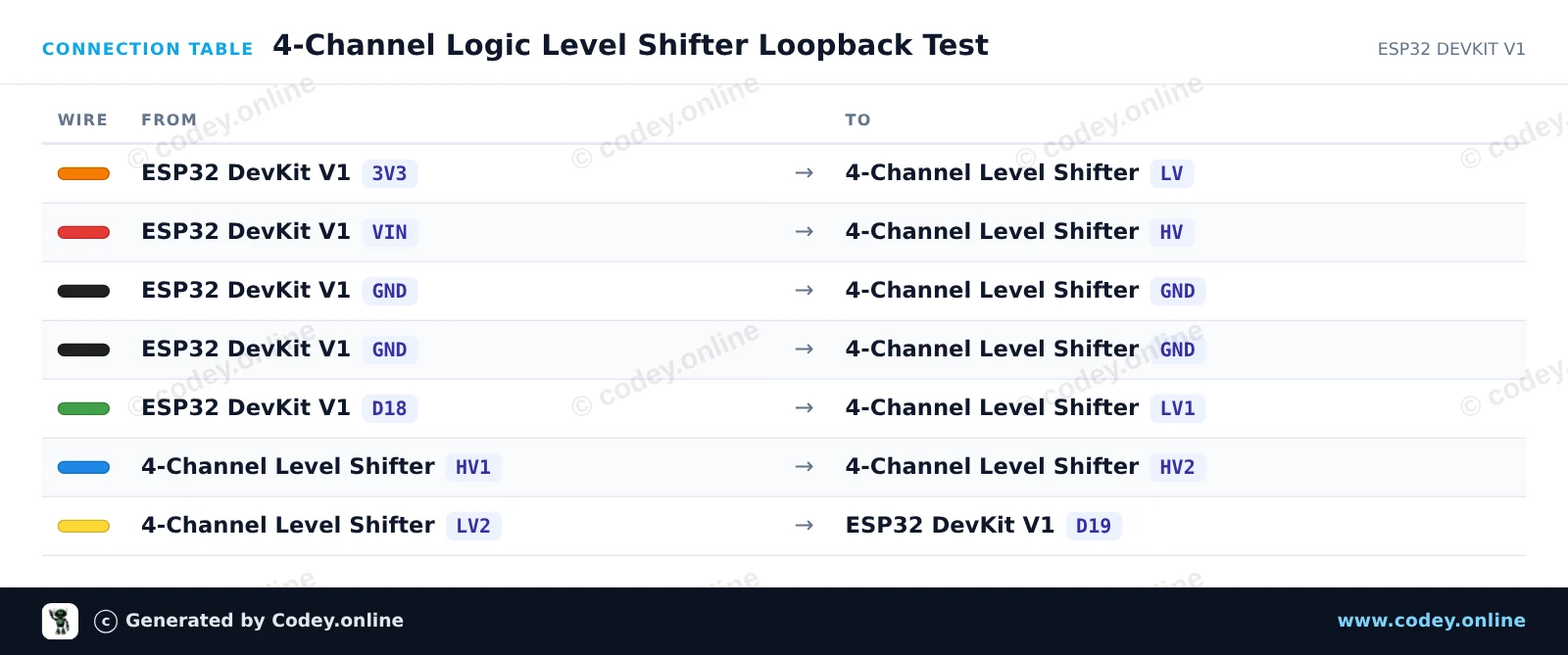
This project demonstrates bidirectional voltage translation with the 4-channel logic level shifter. The ESP32 sends a 3.3V signal into LV1, which is stepped up to 5V at HV1. A jumper links HV1 to HV2, stepping the 5V signal back down to 3.3V at LV2 to be verified by the ESP32.
/*
* ==================================================================
* Generated by Codey.online — https://www.codey.online
* ==================================================================
* Project : 4-Channel Logic Level Shifter Loopback Test
* Board : ESP32 DEVKIT V1 (esp32:esp32:esp32doit-devkit-v1)
* Parts : Logic Level Shifter 4-channel
* Libraries : none (built-in)
*
* Codey Online is an AI-powered browser IDE for Arduino and ESP32.
* Describe your project and Codey writes the code, draws the wiring
* diagram and uploads it to your board, straight from the browser.
* This code is free to use, modify and share, without warranty.
* ==================================================================
*/
// 4-Channel Logic Level Shifter Loopback Demo
// Sends 3.3V pulses on GPIO 18 (LV1), stepped up to 5V (HV1),
// looped to HV2 (5V), and stepped down to 3.3V on LV2 to read on GPIO 19.
const int TX_PIN = 18; // 3.3V Output to LV1
const int RX_PIN = 19; // 3.3V Input from LV2
void setup() {
Serial.begin(115200);
while (!Serial) {
delay(10);
}
pinMode(TX_PIN, OUTPUT);
pinMode(RX_PIN, INPUT);
Serial.println("=== Logic Level Shifter Loopback Test ===");
}
void loop() {
// Test HIGH state
digitalWrite(TX_PIN, HIGH);
delay(10);
int highRead = digitalRead(RX_PIN);
// Test LOW state
digitalWrite(TX_PIN, LOW);
delay(10);
int lowRead = digitalRead(RX_PIN);
// Report status
Serial.print("Sent HIGH -> Read: ");
Serial.print(highRead == HIGH ? "HIGH [PASS]" : "LOW [FAIL]");
Serial.print(" | Sent LOW -> Read: ");
Serial.println(lowRead == LOW ? "LOW [PASS]" : "HIGH [FAIL]");
delay(1000);
}
Wiring diagram and example code generated by Codey.online — https://www.codey.online
Alguns módulos funcionam com I2C ou UART de 3.3V, então este módulo pode converter a tensão se o seu sistema funcionar a 5V.(por exemplo, o seu Arduino de 5V)
Além disso, tem um regulador de tensão incorporado que converte 5V para 3.3V até 100mA, também útil se precisar de alimentar um módulo com 3.3V que não tenha regulador de tensão incorporado.
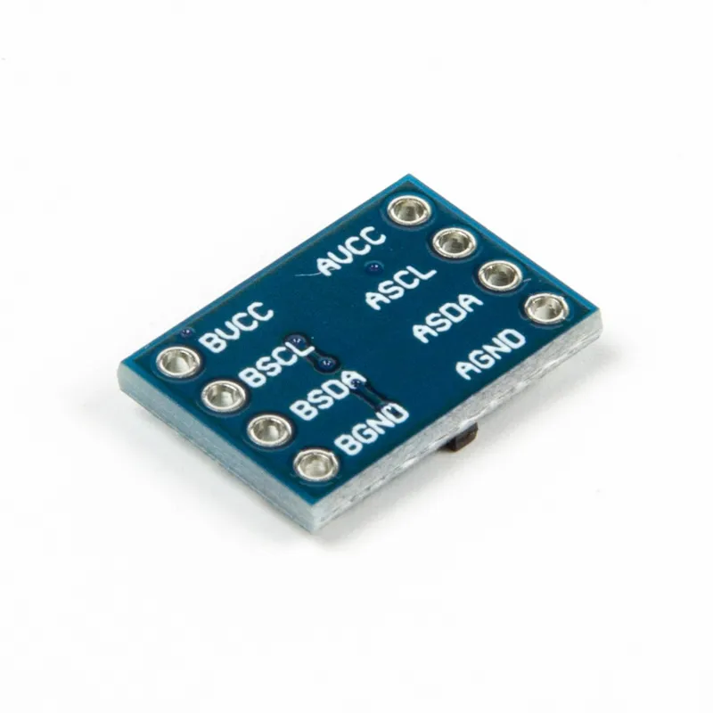
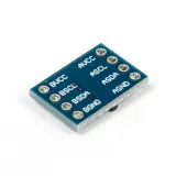
Os pinos estão indicados na parte inferior:
Ligar AVCC a 5V
Ligar ASCL ao pino SCL/TX do sistema de 5V
Ligar ASDA ao pino SDA/RX do sistema de 5V
Ligar AGND ao GND do sistema de 5V
Ligar BVCC a 3.3V do sistema
Ligar BSCL ao pino SCL/RX do sistema de 3.3V
Ligar BSDA ao pino SDA/TX do sistema de 3.3V
Ligar BGND ao GND do sistema de 3.3V
Este módulo é, em princípio, apenas adequado para passar de 5V para 3.3V. O regulador de tensão só consegue converter 5V para 3.3V.
Se o seu sistema for de 3.3V e quiser ligar um módulo de 5V, deve ligá-lo da seguinte forma:
Ligar AVCC a 5V (linha de alimentação de 5V)
Ligar ASCL ao pino SCL/TX do sistema de 5V
Ligar ASDA ao pino SDA/RX do sistema de 5V
Ligar AGND ao GND do sistema de 5V
BVCC não ligar
Ligar BSCL ao pino SCL/RX do sistema de 3.3V
Ligar BSDA ao pino SDA/TX do sistema de 3.3V
Ligar BGND ao GND do sistema de 3.3V
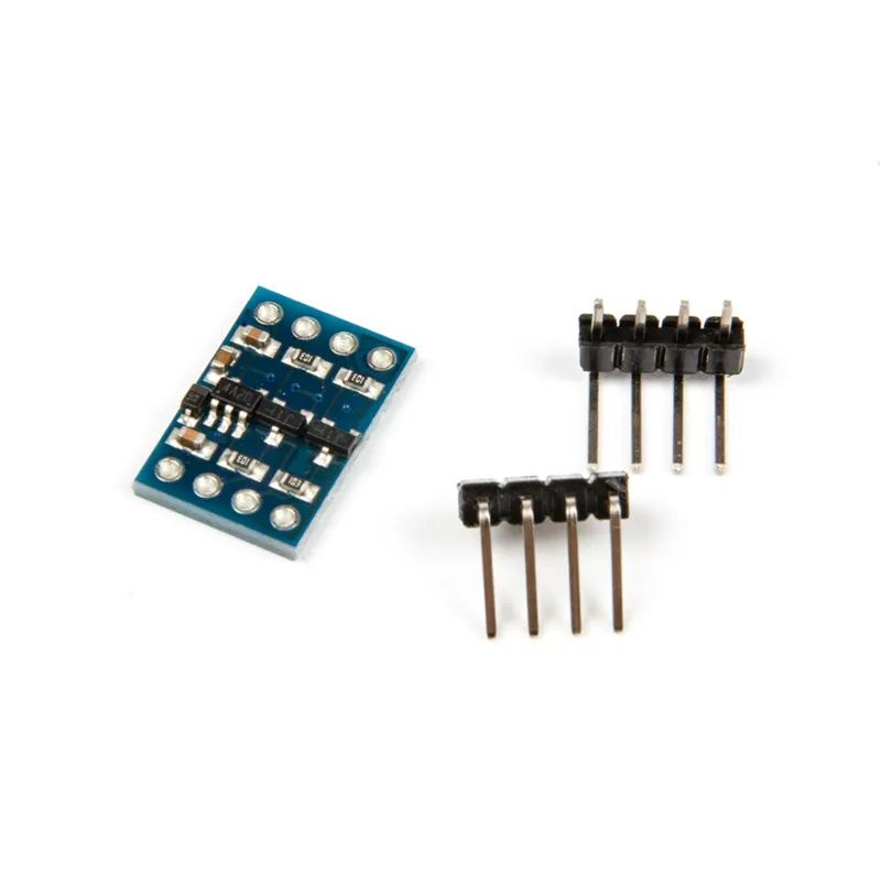
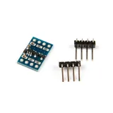
Atenção: Os headers de pinos para este módulo ainda não estão soldados. Se pretender usar os headers, terá de os soldar você mesmo.

| Interface | I2C |
|---|---|
| Tensão de entrada | 5V |
| Tensão de saída | 3.3 V |
| Corrente | 100mA |
funciona perfeitamente!
Conforme a descrição
Não ficas satisfeito? Tens 30 dias após a receção para devolver o produto.
Tudo sobre devoluções
Conversor de Nível Lógico I2C-UART Bidirecional 5V-3.3V 2 canais